
A Beginner's Guide to CNC Programming: Learning G-Code and M-Code
- ved singh

- Jan 27
- 5 min read
Updated: Feb 9
A Beginner's Guide to CNC Programming: Learning G-Code and M-Code
Welcome to the world of CNC (Computer Numerical Control) programming! If you've ever wondered how those massive machines in a workshop know exactly how to cut a piece of metal into a complex part, the answer is G-code and M-code. Think of it as the language we use to talk to the machine.
This guide will break down the basics, provide you with essential code lists, and walk you through a simple example, line by line.
Understanding the CNC Machine's World
Before we dive into the codes, it's crucial to understand how a CNC machine sees the world. It uses a 3D Cartesian coordinate system to locate every point on the workpiece.

X-Axis: Typically moves left and right.
Y-Axis: Typically moves forward and backward.
Z-Axis: Moves up and down, controlling the depth of the tool.
The "Origin" or "Part Zero" (X0, Y0, Z0) is a reference point you define on your workpiece from which all other movements are calculated.
Your Essential G-Code and M-Code "Cheat Sheet"
G-codes (Geometric codes) tell the machine how to move, while M-codes (Miscellaneous codes) tell it what to do, like turning the spindle on or off. Here is a list of the most common codes you'll use in CNC milling and turning.
Common G-Codes (Movement & Geometry)
G-Code | Function | Description |
G00 | Rapid Positioning | Moves the tool as fast as possible to a coordinate. Never used for cutting. |
G01 | Linear Interpolation | Moves the tool in a straight line at a specified feed rate (cutting speed). |
G02 | Circular Interpolation (CW) | Moves the tool in a clockwise arc. |
G03 | Circular Interpolation (CCW) | Moves the tool in a counter-clockwise arc. |
G17 | XY Plane Selection | Selects the XY plane for arcs (standard for most milling). |
G20 | Input in Inches | Sets the machine to read units in inches. |
G21 | Input in Millimeters | Sets the machine to read units in millimeters. |
G28 | Return to Home | Moves the tool to the machine's reference (home) position. |
G40 | Cancel Cutter Compensation | Turns off cutter radius compensation. |
G41 | Cutter Compensation Left | Offsets the tool to the left of the programmed path. |
G42 | Cutter Compensation Right | Offsets the tool to the right of the programmed path. |
G43 | Tool Length Compensation | Applies a positive offset for the tool's length. |
G54 | Work Offset #1 | Selects the first standard work coordinate system (your part zero). |
G90 | Absolute Programming | Coordinates are all relative to the fixed part zero (X0, Y0, Z0). |
G91 | Incremental Programming | Coordinates are relative to the current tool position. |
Common M-Codes (Machine Functions)
M-Code | Function | Description |
M00 | Program Stop | Pauses the program until the operator presses the start button. |
M01 | Optional Stop | Pauses the program only if the "Optional Stop" switch on the machine is on. |
M03 | Spindle On (CW) | Starts the spindle rotating in a clockwise direction. |
M04 | Spindle On (CCW) | Starts the spindle rotating in a counterclockwise direction. |
M05 | Spindle Stop | Stops the spindle from rotating. |
M06 | Tool Change | Executes a tool change sequence. |
M08 | Coolant On | Turns on the flood coolant. |
M09 | Coolant Off | Turns off the coolant. |
M30 | Program End | Ends the program and rewinds it to the beginning. |
A Simple Part Example: Cutting a Square
Let's put this knowledge to use. We're going to write a program to mill a 50mm x 50mm square contour.
First, let's look at the "blueprint" for our part. We'll set the bottom-left corner as our origin (X0, Y0).

The G-Code Program
Here is the complete program to cut this shape. Don't worry if it looks like gibberish right now; we'll break it down in the next section.
G-Code
O1001 (SQUARE CONTOUR EXAMPLE)
N10 G21 G90 G40 G49 G80 (SAFE START BLOCK)
N20 T01 M06 (TOOL CHANGE TO TOOL 1)
N30 S2000 M03 (SPINDLE ON CW AT 2000 RPM)
N40 G54 G00 X-10. Y-10. (RAPID TO START POINT OUTSIDE PART)
N50 G43 H01 Z25. (APPLY TOOL LENGTH OFFSET, RAPID TO SAFE Z)
N60 Z5. M08 (MOVE TO CLEARANCE Z, COOLANT ON)
N70 G01 Z-1. F150. (PLUNGE INTO MATERIAL AT FEED RATE)
N80 G41 D01 X0. Y0. F500. (COMP ON LEFT, MOVE TO ORIGIN)
N90 Y50. (CUT TO TOP-LEFT CORNER)
N100 X50. (CUT TO TOP-RIGHT CORNER)
N110 Y0. (CUT TO BOTTOM-RIGHT CORNER)
N120 X-10. (CUT PAST ORIGIN TO COMPLETE SHAPE)
N130 G40 G01 X-20. Y-20. (COMP OFF, MOVE AWAY FROM PART)
N140 G00 Z25. M09 (RETRACT Z TO SAFE HEIGHT, COOLANT OFF)
N150 M05 (SPINDLE STOP)
N160 G91 G28 Z0. (RETURN Z TO HOME)
N170 G28 X0. Y0. (RETURN X AND Y TO HOME)
N180 M30 (PROGRAM END)
Line-by-Line Explanation
Let's walk through the program to understand exactly what the machine is doing at each step.
O1001 (SQUARE CONTOUR EXAMPLE): This is the program number (O1001) and a comment in parentheses describing the program. Comments are ignored by the machine.
N10 G21 G90 G40 G49 G80: This is a "safe start block." It sets the machine to a known state: metric units (G21), absolute positioning (G90), and cancels any active cutter compensation (G40), tool length offsets (G49), or canned cycles (G80).
N20 T01 M06: Selects Tool #1 (T01) and performs a tool change (M06).
N30 S2000 M03: Sets the spindle speed to 2000 RPM (S2000) and turns the spindle on in a clockwise direction (M03).
N40 G54 G00 X-10. Y-10.: Activates work coordinate system #1 (G54) and rapidly moves (G00) to a position outside the part at X-10mm, Y-10mm.
N50 G43 H01 Z25.: Applies tool length compensation for Tool #1 (G43 H01) and rapidly moves the Z-axis to a safe height of 25mm above the part.
N60 Z5. M08: Rapidly moves Z down to 5mm above the part and turns on the coolant (M08).
N70 G01 Z-1. F150.: This is the first cutting move! It moves the tool down in a straight line (G01) to a depth of -1mm (Z-1.) at a slow feed rate of 150 mm/min (F150.) for plunging.
N80 G41 D01 X0. Y0. F500.: Turns on cutter compensation to the left (G41) using the diameter offset for Tool #1 (D01). It then moves to the bottom-left corner (X0, Y0) at a cutting feed rate of 500 mm/min (F500.).
N90 Y50.: Cuts a straight line up to the top-left corner (X0, Y50). Since X doesn't change, we don't need to write it.
N100 X50.: Cuts a straight line to the top-right corner (X50, Y50).
N110 Y0.: Cuts a straight line down to the bottom-right corner (X50, Y0).
N120 X-10.: Cuts back past the start point to X-10 to ensure the corner is fully cut.
N130 G40 G01 X-20. Y-20.: Turns off cutter compensation (G40) and moves linearly (G01) away from the part to X-20, Y-20.
N140 G00 Z25. M09: Rapidly retracts the tool to a safe Z-height of 25mm and turns off the coolant (M09).
N150 M05: Stops the spindle.
N160 G91 G28 Z0.: Switches to incremental mode (G91) temporarily to send the Z-axis to its home position (G28 Z0.).
N170 G28 X0. Y0.: Sends the X and Y axes to their home positions.
N180 M30: Ends the program and resets it to the start.
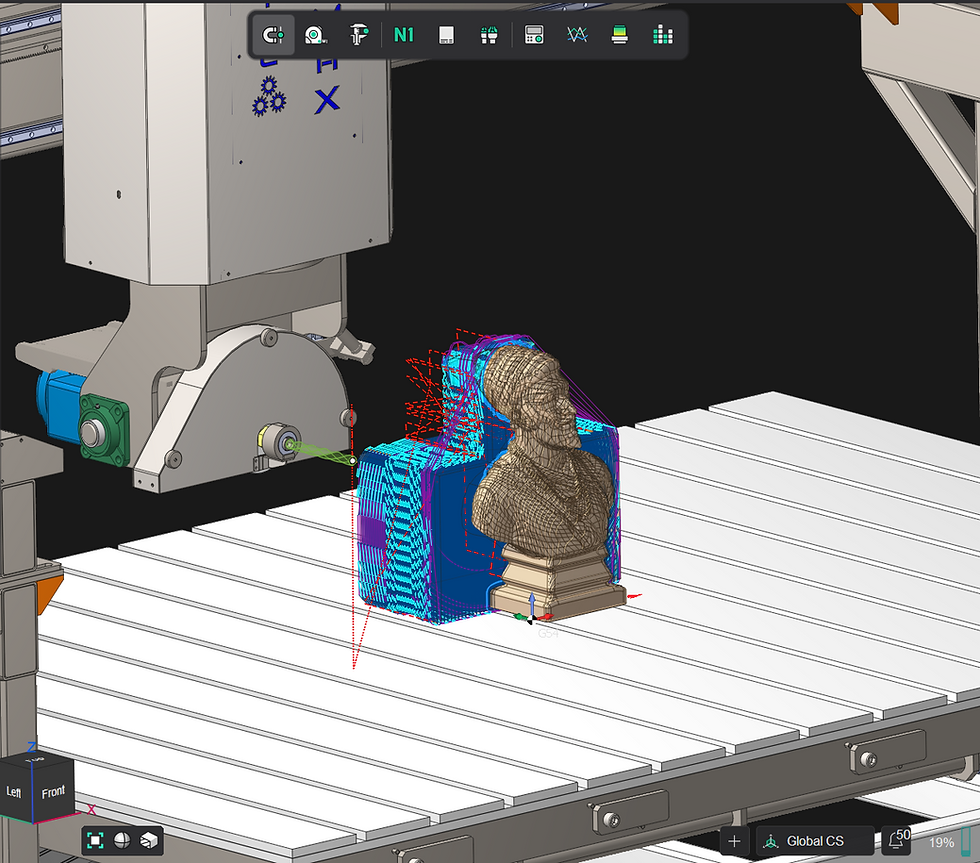
This is a visual representation of what the toolpath might look like in a simulator:


Comments